Tech Support & Replacement Parts // 877.522.3364

Compatibility/Hitch Options

FOR THE PLOW WITH HITCH KIT INCLUDED


NOTE - This is normally a bolt-on assembly.
• Converts your existing ¾” utility hole or your square weak 1 ¼” receiver over to a strong square receiver hitch. This is mostly for Honda and Polaris work/ranch type machines.


IMPORTANT - INSTALLATION NOTES FOR GroundHog MAX HITCH KIT


The concepts/instructions/pictures of how you can install the GroungHog MAX hitch kit (OPTION #3) for a Honda and Polaris…many
times can be used on other machines.


If your frame design is similar to Honda/Polaris (bottom of frame being fairly flat or having some existing “cross members”) you may be able to use the GroundHog MAX kit. The concept of attaching a bolt through the frame or using strong hose/pipe clamps to attach to the frame can sometimes be utilized as the front anchor point. Your main anchor point is the existing ¾” utility hole in the back or weak 1 ¼” receiver. Well placed tack welds, u-bolts, or square u-bolts can be used also.


EXAMPLE - Many Bombardier/Can AM usually have a strong flat “channel type” for a frame.


NOTE - Keep in mind that normally our long receiver hitch tube can be drilled/notched etc. to make an installation work without making the tube too weak to use. Use common sense and/or call us. Our kit is heavy duty using a ¼” wall tube. This makes our collared tube very strong.


NOTE - Customers are using this hitch and plow on 1990’s machines and even other power sources. Our GroundHog MAX hitch kit is considered a universal "type" of hitch kit because it fits many machines…but it is NOT a universal hitch kit for ALL the hundreds of different frames out there.


IMPORTANT - BE ADVISED ON AFTERMARKET HITCHES


Many customers buy a NO KIT VERSION of the plow and then buy an aftermarket hitch that is specific for their year, make, model, and
manufacturer of machine. Polaris and Honda owners most times prefer to use our kit (this kit fits some others units also).


2014-2019 Honda’s - Rancher and Foreman owners both should NOT buy our GroundHog MAX Kit version of the plow. They should buy the
NO KIT version and then buy an aftermarket hitch by Strong Made (RH119). See link below.


IMPORTANT - 2015 & NEWER POLARIS RANGERS If you do use the plow be careful of your hitch… plow less aggressively by up/down adjustment settings ( in 1” increments). Set your tractor pin so you do not use too much weight. Remember on any side-by-side like a Ranger, you have “double” the weight of a 700 lbs. ATV.


All this weight is not required for the plow to work. We recommend a DIY brace below to be sure. See image P6.


Installation Video for Polaris


Installation Video for Honda


GroundHog MAX Hitch Kit - Anchoring / Bracing


If you're using the GroundHog MAX Hitch Kit, remember this... The main anchor point… and load of the hitch system is (at the back) where your factory 3/4” utility hole is used, or where the 1 1/4” factory hitch assembly is used.


The secondary anchor point can be anywhere along the 20 inches of the receiver tube; if needed, you can use 25A extension tube for more length. This anchoring is towards the front, along the bottom of the frame. NOTE: this extension tube (25A) can be turned horizontal if you need to run a strap through it. The secondary anchor point primary purpose is to keep the receiver tube level and to prevent left to right movement.


NOTE - Some ATVs have an unusual hole pattern/frame. In these cases, the hole is not centered, but 2 holes will be side-by-side and off centered. A couple of strong, well placed screw-type hose/pipe clamps can be used. Place them under the receiver tube and up over the frame, then secure. This will hold our receiver tube tightly to the frame. Also, tack welds are sometimes used to secure our receiver tube to the frame. Click here to view a video of a newer Polaris Installation.


CAUTION - for the option using our kit (even though this hitch setup is attached in two places and distributes the up pressure on 20+ inches of your frame) still start plowing ONLY using part of your weight.


General Tips for Installing the GroundHog MAX with Hitch Kit


Normally a bolt on assembly for most Hondas, Polaris, and some other machines too. NOTE: On some models you may need to buy and use hose clamps/pipe clamps to attach our long hitch tube to the bottom of your frame. Watch installation on a Honda.


The GroundHog MAX hitch receiver system is strong, as it runs under the machine and is attached in 2 places. So when you are running over roots, rocks, sticks, etc. you are pushing up on 20-inches of the machine’s frame. The plow’s T-head can be turned upside down or right side up.


Remember, your primary hookup is at the back, either utilizing the existing utility hole as the main anchor point or the 1 ¼” assembly being the main anchor point. Your secondary hookup on the front of the receiver tube only holds the tube level and keeps it from going L/R so it does not require much to secure it in place.


If you buy the plow with the kit, there is hardware included in the box. The main piece of the kit is (part 25) a 20-inch long, ¼” wall thick, collared receiver tube. The kit includes various other hardware including bolts/nuts/washers, tongue straps, spacers. Also included in the kit is a 9” long extension tube (25A) that slides in the long receiver tube (part 25) to make it longerto allow you to extend to a hole or cross member if needed.


There is an additional 5” long receiver tube (Figure 5 or part 17). Be careful if you use this receiver because it can only be properly used as a hitch receiver if it is DIY braced. Any bracing needs to offset some of the up pressure the plow puts on the machines hitch setup.


REMEMBER - In some cases, you may need to purchase some strong hose/pipe clamps and/or strong nylon straps/tie wraps. These can be used to cinch the receiver tube up to the bottom of your frame/skid-plate. They may or may not be needed for your application.


ATTACH WITH BOLT ON/CLAMP ON ASSEMBLY

Bolt On/Clamp On Assembly - The GroundHog MAX with Hitch Kit converts your existing ¾” utility hole or weak 1 ¼“ square receiver over to a strong 2” receiver (primarily Honda and Polaris applications . It can also fit some other units with the same installation concept.


NOTE - Our GroundHog MAX hitch kit is considered a universal "type" of hitch kit because it fits many machines, but it is NOT a universal hitch kit for ALL the hundreds of different frames out there.


NOTE - The clamps and straps are not provided in the GroundHog MAX Hitch KIT, but this hardware can be an easy fix for your hookup. Always install your spacers and washers where needed. It is always much stronger to tighten metal to metal to secure. The receiver tube does not have to be perfectly level nor does it have to be perfectly straight to plow. The GroundHog MAX collared receiver tube is made out of ¼” steel. It has plenty of integrity and strength to be drilled/notched/altered etc. and still do the job.


HOSE/PIPE CLAMPS
• They should be approx. 1/2” wide.
• These are like you would put on a cars heater hose and screw down to tighten.
• Can be put together for longer lengths.
• Can come wider as well. They also come in stainless steel for strength.


GENERAL NOTES ON STRAP TIES/NYLON STRAPS
• Should be at least 1/2” wide, but just basic standard issue versions have been used with success.
• They can be put together for longer lengths.
• They can come wider as well.
• They also come in industrial strength.


TAKE TO FABRICATION SHOP OR WELDER FOR ATTACHMENT


This may be necessary in some cases, ie: Pre-year 2000 machines and others. (normally for $35 to $50 they can fix you up).


NOTE: BE SURE TO ADVISE them that the plow has “up Pressure” not tongue weight.


IMPORTANT - IF YOU DECIDE TO USE BOLT/ON ASSEMBLY OR USE A FABRICATION SHOP, SEE BELOW FOR YOUR HARDWARE options.


 A) You can buy and use a Collared 2“ square receiver in 6” long and 12” long versions.


 B) You could take our GroundHog MAX kit to the Fabrication shop (if you did already purchase the kit and the bolt on application will not work for your unit). In most cases, they can utilize the kit’s hardware/hitches for attaching it.


DO IT YOURSELF 


Pre-year 2000 machines and most others.


NOTE - BE SURE TO take into consideration that the plow has “up pressure,” not tongue weight.


ATTACHMENT

 1) Find a level spot and carefully back your rear tires up on 4” ramps (or a 4” alternative, like a piece of 4x4 wood that spans the 2 rear tires). Be advised that if you use a taller ramp it makes it harder to determine a proper depth setting for the plow. If ramps are not available or impractical, it is acceptable to back the rear tires onto a sturdy surface that elevates them by 4 inches. A section of 4x4 wood is a good example of an improvised lift. Be sure to follow all safety steps in order to prevent injury. It may be easier to leave a 4x4 block at your food plot). DO NOT just lift up the machine’s rear end to install. This does not work and will only stretch out your suspension.


 2) Attach once the machine is on the blocks/ramp, turn your machine off, put it in park and lock the parking brake, and chock the wheels. Slide your fully assembled plow (T-head) into your ATV receiver and lock it in with the first tractor pin. Now pull the second tractor pin out of the T-head to set the up/down adjustment. To start, allow the disc assembly to touch the ground from its position on the 4” blocks, slide the disc assembly back up two holes, and re-install your second tractor pin. This will allow the discs to touch the ground and be weighted enough to plow once the machine is backed off the blocks. These adjustment holes are in 1” increments, and only one tractor pin is needed in the T-head for locking the up/down adjustment in place. Remember this important adjustment note: The T-head can be turned right side up for machines with higher ground clearance or upside down for machines with lower ground clearance. On all machines ONLY use part of your weight. A lot of the “cut” is in turns and maneuverability. NOTE: On any unit always start out less aggressive. If your model’s 2” hitch has a factory split on its side, you need to re-enforce it.


Remember, when handling the GroundHog MAX ATV / UTV Disc Plow always be extremely careful. There are sharp edges and moving parts. Failure to use caution may result in serious injury.


OPERATION - MUST READ


 1) Make sure the plow is facing in the proper direction before using. The plow has a slight arrowhead shape. The point should point backwards going away from the machine.


See pictures below.

Image titleImage title


 2) Make sure you start off less aggressively. Do not use too much weight because a lot of the cut is in turns and maneuverability. Normally you can find an adjustment hole that allows enough weight of the plow for it to work but run your machine in 2-wheel drive.


ADJUSTMENT


 1) The combined weight of the ATV (700 lb plus) and your weight (200 lbs.) is now putting direct downward force on the plow, allowing it to work. Remember a Side-By-Side/UTV’s weight is 1200-1500 lbs. (double that of an ATV).


Be CAUTIOUS to only use part of your weight.


 2) Long-Term Adjustment: after some experimentation, you will determine which hole works best for your particular setup. Normally the next time you use the plow you can use the same hole adjustment setting unless some conditions have changed. Another adjustment option some customers prefer is to set the adjustment hole to plow very light in the beginning then back up on the ramps again and let it down another hole. Using either of these approaches will "gradually" plow your plot down about 3-4” deep. The height adjustment needed will vary according to your year, make, model, tires, etc. and may take a few tries to properly adjust. Start-off less aggressively and adjust as needed.


 3) Left/Right Movement: As you are adjusting, you may notice a lot of left to right “play” in the plow where the axle assembly goes into the up/down adjustment tube. This is intentional and allows the plow to float and adjust to uneven ground.


 4) Plowing Production and Conditions: The time required to plow a spot will be determined by how hard the ground is (roots, rocks, grass systems, wet/dry, and ground clutter) The tougher the conditions the more passes you have to make. Plow in looping circles and figure eights to maximize your cut, and the gap between the middle discs will go away if you plow in this manner. However, plowing straight will also work. If you determine you are not using enough weight you can adjust the T-head down a hole.


 5) The optimal plowing speed is approximately 5mph. Plowing forward in oblong circles and figure eights is much faster and more productive. You do not have to waste time stopping and shifting. Be sure to slow down when making turns with the plow engaged.


MAINTENANCE


Owner should check and tighten (if necessary) all hardware after the first half-hour of operation. The break in stage of the plow can cause minimal loosening of hardware. Retighten hardware as necessary.


After the first use, be sure to check the disc blades for side-to-side movement. Some side-to-side movement is normal. If there is excessive movement tighten the castle nut and re-pin. Discs sometimes do not spin properly until after approx. 5 minutes of use. Keep in mind that discs will not free spin like a bike wheel. You should continue to check this after each use to get the longest life out of your GroundHog MAX ATV / UTV Disc Plow. Discs do not need to be sharpened, oiled, or greased. Lightly spray down the complete unit with WD-40…if stored for any length of time.


The plow will penetrate to approximately 4” deep. Based on soil conditions, it may take several passes to achieve this depth. The plow can be adjusted to a shallow depth setting to cover seeds.


Using Reverse: The plow can be backed up with the plow engaged (only if necessary), but it does put more pressure on your hitch. It does not plow well this way (since the discs would face the wrong direction). Use; reverse only when necessary for maneuverability. Note: Sometimes in certain soils, soft dirt, and if elevation is present reverse is not very useable. If you have to use reverse the plow will track with your vehicle.


Transport Mode: Due to how the rear of some machines are laid out (racks, mufflers, frame etc.) transport mode does not work on all machine hitches. In this case, another easy option is to strap the GroundHog MAX to the front or back rack for transportation.


Storage: Remove the plow from your ATV, visually inspect the plow, tighten and lubricate if necessary. Place in a safe storage area. Proper storage will prevent disc and bearings from rusting and locking up.


2014-2018 HONDA RANCHERS AND FOREMAN

Rancher and Foreman owners both should NOT buy our GroundHog MAX Kit version of the plow. They should buy the NO KIT version and then buy an aftermarket hitch by Strong Made (RH119). Click this link - https://strongmade.com/rh119-rear-receiver-hitch-for-honda-foreman-2014-2019-and-rancher-2014-2019.html


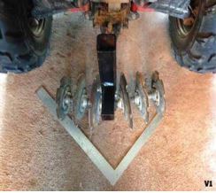
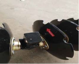
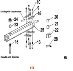
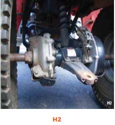
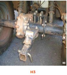
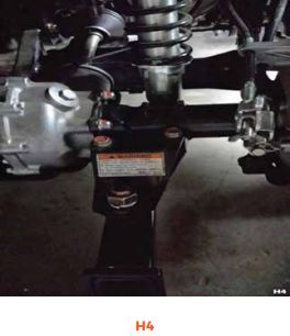
The GroundHog MAX Receiver Kit will be attached in 2 places. SEE pictures H1- 2- 3- 4 for most work/ranch related Hondas.


INSTALL NOTE - These hose/pipe clamps and tie wraps/straps discussed may be an easy way to attach BOTH older and newer Hondas. Not included in box.

Honda has (2) MAIN types of frames. The GroundHog MAX KIT will work on MOST. There are a few exceptions that may require and extra steps.


Honda’s main anchor point on (BOTH OLDER THAN 2007 AND NEWER THAN 2008 FRAMES) is always the ¾” utility hole in the (rear)…the receiver tube bolts to the machine by utilizing your ¾” existing utility hole with a ¾” bolt/nut. (See diagram H 1)


OLDER THAN 2007 TYPE FRAMES MAIN ANCHOR POINT


FOLLOW STEP #1 - See pictures H1 2 3.


STEP #1 To Assemble Honda’s rear main anchor point, install the 21” collared receiver tube (Part 25) underneath the factory utility hole assembly. Secure it to the ATV by placing a ¾” bolt (part 15) through (part 25) and the factory utility hole. Place lock washer (part 23) and nut (part 24) onto bolt (part 15) tighten loosely, filling any voids with washers/spacers as needed.


OLDER THAN 2007 TYPE FRAMES YOUR SECONDARY ANCHOR POINT SEE PICTURES H1, 2, & 3


STEP #2 HONDA secondary receiver tube attachment point can be anywhere along the 20 inches of the receiver tube. If needed, use 25A extension tube for more length. This is towards the front, along the bottom of the frame on many Hondas and on some others it is ATTACHED/SANDWICHED with a bolting assembly to the existing standard rectangle or round shaped cross member on the HONDA. Hardware provided.


NOTE - On the GroundHog MAX hitch kit the primary purpose for the secondary attachment point is to keep the receiver tube level and prevent left/right movement. It does not take too much to hold it. To install, place the (1) ½” spacer (part 22) or ¼” spacer (can be used under the 1 ½” winged spacer block on top of the 21” receiver tube (part 25) at the point where the ATV has a left to right cross brace. To make part 25 as level as possible fill any voids with other spacers (parts 20, 21) or washers if needed. In some cases, where voids are large you may use the 5” receiver tube (part 17) as a spacer. All parts may not be used.


NEWER THAN 2008 TYPE FRAMES


HONDA’s REAR main anchor point is the same as older Hondas. FOLLOW STEP #1 above.


HONDA’s secondary anchor point with a wider (5-6” concave type) cross member. You can attach anywhere along the 20 inches of the receiver tube. If needed, use 25A extension tube for more length. This is towards the front along the bottom of the frame. Due to this frame being different, hose/pipe clamps may need to be used. (not provided)
Hose/pipe clamps used should be approx.-1/2” wide, (2) 18-20” long clamps for Honda. You can put 2 short ones together to make a long one. There are several ways customers traverse the cross member.


 1) Go straight up and over or Crisscross the clamps as you go up and over the cross member. Install one clamp on each side of the receiver tube.
 2) In some cases, strap through the 9” extension tube part 25a. Part 25a can turn sideways so the 5/8” hole is horizontal to the ground. You can run the clamp through the hole and go up and over the cross member.
 3) In some cases, you can 2 of the tongue straps that are provided on the bottom of the receiver tube. Run your hose clamps/straps through these on each side of the tube and go up and over the wider cross member.


NOTE - In picture H4, the hitch receiver tube goes all the way under the existing wide cross-member.
NOTE - THE GroundHog MAX KIT FITS SOME older (pre-2000) HONDA year/make/models… Having an existing workable cross member is
the key.


Image titleImage title


Image titleImage title


Watch an installation video for Hondas.

ALL POLARIS- the main anchor point is in the (rear) of the receiver tube and attaches to the machine by either:

 A) Utilizing a ¾” bolt through the ¾” utility hole (OLDER TYPE FRAMES older than 2008).

 B) Assembling under the 1 ¼” weak factory square hitch assembly (FOR NEWER TYPE FRAMES 2009 and newer).


 C) With extra steps, most Magnums, some Explorers, and some chain drives can work. Call tech support for more information.


NOTE - On the GroundHog MAX hitch kit, the primary purpose for the secondary attachment point is to keep the receiver tube level and prevent left/right movement. It does not take too much to hold it. Attachment can be anywhere along the 20 inches of the receiver tube. If needed, use 25A extension tube for more length. This is towards the front, along the bottom of the frame. This is a very strong assembly since it attaches in 2 places. It distributes the up pressure on 20 inches of your frame. The receiver tube does affect ground clearance but is a bolt-on attachment that can be removed. The installation instructions above cover most Honda, Polaris, and even some other machines,
but not all.


Polaris has (2) types of frames. The GroundHog MAX KIT will work on MOST.


 1) OLDER that 2006 has just a ¾ “utility hole in the rear.
 2) NEWER THAN 2007 has a weak 1 ¼” square receiver. See pictures below.


NOTE - Polaris Rangers - See picture picture P6 for reference.


NOTE - The receiver will be attached in 2 places. See picture P1 and pictures P2. THIS IS A POLARIS HOOK-UP WITH THIS “OLDER TYPE FRAME” (has a ¾” utility hole only).


**********************


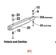
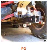
OLDER MODEL POLARIS  - 2006 and older


This is for an “older model” polaris frame (2006 and older). See pictures P1 and P2. The following steps are if your Polaris "rear main anchor point' has a 3/4 utility hole (where a ball hitch goes).


STEP 1 - Install the 21” collared receiver tube (Part 25) underneath the factory utility hole assembly. Secure it to the ATV by placing a ¾” bolt (part 15) through part 25 the collared end and the factory utility hole. Now put the nut/washer on loosely at this point.


STEP 2 - Place lock washer (part 23) and nut (part 24) onto bolt (part 15). Tighten loosely filling any voids with washers/spacers as needed. See pictures P1 and P2. The secondary anchor point can be anywhere along the 20 inches of the receiver tube. If needed, use 25A extension tube for more length. This is towards the front, along the bottom of the frame. Reference pictures P4 and P5 for another possible option with clamps for the older units also.


STEP 3 - Slide the 9” extension tube (part 25-a) into receiver tube (Part 25). Place 5/8” bolt (part 28) medium length or (part 8) short length depending upon space through the tube and frame (utilizing the existing hole in the middle of the frame of your ATV. Install the bolt going upwards through the frame and add a washer on top of the frame for strength if possible. If you need to drill a hole in our tube you can do so. You can drop down and use a smaller bolt or drill even a 7/16” hole through the tube and/or frame if you need to for the attachment.


STEP 4 - Fill any voids with a washer/spacer between extension tube and the frame. The, gradually tighten all nuts securely on both ends.


***************************


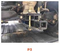
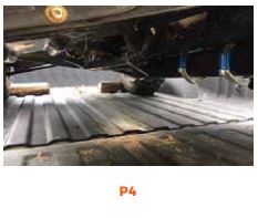
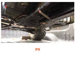
NEWER MODEL POLARIS - 2007 & NEWER

Click here for a video showing an installation of a GroundHog MAX with Hitch Kit on a new model Polaris (on a manufacturer's existing weak 1 1/4' square receiver tube.) This should work on most of the newer Polaris as well as machines with this type of frame setup.


If your polaris has an existing 1 ¼" square receiver, this is a “newer model type” different polaris frame. See pictures P3, P4, and P5 for Polaris that have a weak factory 1 ¼” square receiver hitch assembly in back (not a utility hole). Remember try to keep the tube as close to the rear of the unit as possible without interfering with anything. 


STEP 1 - POLARIS REAR MAIN ANCHOR POINT Install (2) long 5/8“ bolts (part 16) up through the bottom tongue strap (part 18) and the existing triangular chain keeper slots 1 ¼“ Polaris factory receiver hitch. Put another tongue strap (part 18) on top of the assembly. Only tighten loosely at this point. Remember to keep the end of the GrounHog MAX receiver tube as close to the end of the factory 1 ¼" receiver as possible.


STEP 2 - Secondary anchor point can be anywhere along the 20“ of the receiver tube. If needed, use 25A extension tube for more length. This is towards the front, along the bottom of the frame. On these newer Polaris frames, you may attach the receiver tube several different ways according to the way your frames hole pattern is designed. See pictures P4 and P5 below.


A) Attach the receiver tube with a bolt through an existing hole in the center of the frame.
B) Cinch the tube up to the frame with strong hose/pipe clamps (not included in the kit) in one place or possibly many times there are two sets of two holes (total of 4 holes).


NOTE - Some machines have an unusual hole pattern/frame where the hole is not centered. In many of these cases you will find two holes side-by-side and off center. A couple of strong, well-placed screw-type hose/pipe clamps can be used. Place them under the receiver tube and over the frame, then secure. This will work well to hold our receiver tube tightly to the frame. Also, tack welds can be used to accomplish this. THIS APPROACH may be used on some Hondas and other machines too. Some customers additionally secure with strong nylon tie wraps/straps to do this. If you need to drill a hole in our tube you can do so. You can drop down and use a smaller bolt or drill
even a 7/16“ through the tube and/or frame if you need to for the attachment.


STEP 3 - Gradually tighten all nuts/clamps/straps securely on both 21“ receiver tube (part 25) into 9“ extension tube assembly (part 25-a).


NEXT - Place the GroundHog MAX plow T-head (part 12) into the 21” receiver tube (part 25) and secure with provided tractor pin (part 13) and cotter key (part 14). T-head can be turned upside down also if needed.


Image title

Image title

Image title


Image title

Image title


Image title


PLOW WITHOUT HITCH KIT


Option #1 - Plug & Plow
Fits units with existing strong square 2” hitch receiver.


Option #2 - Purchasing a Strong Aftermarket Receiver
Fits any ATV (year 2,000 and newer) with the purchase of a strong square 2” receiver (order year, make, model specific).


NOTE - These aftermarket hitch kits you can buy are engineered to re-enforce and convert your existing hitch setup into a strong square
2” receiver. These aftermarket hitch kits are bolt on assemblies.


NOTE - 1999 and older see Option #3, #4, or #5. Call us if you have any questions at 877-522-3367.


AFTERMARKET HITCHES AND LINKS TO FIND THEM - FOR OPTION #2
These aftermarket hitches are year/make/model specific and normally go back to about year 2000. They convert your ATV/UTV's existing utility hole or receiver hitch (many have a weak 1 ¼”) to a strong, forward braced, 2” square receiver. Once this hitch is installed your ATV/UTV becomes “Plug and Plow“ ready! BEWARE: The "cheap" 2” receivers that are attached to the utility hole with one bolt, or the "cheap" 2” receiver that slides into the weak 1 1/4” receiver DO NOT WORK very well if used alone and will bend. To work at all they must be reinforced to make them stronger and offset the up-pressure of the plow. Polaris and Honda owners most times prefer to use our kit but they still have the same option to buy these aftermarket hitches for their unit.


CAUTION - 2014 & Newer Hondas: Rancher and Foreman owners both should NOT buy our GroundHog MAX Kit version of the plow. They should buy the NO KIT version and then buy an aftermarket hitch by Strong Made (RH123). Click here - https://strongmade.com/rh123-rear-receiver-hitch-for-honda-foreman-sra-500520-2014-2022-and-rancher-sra-2014-2022.html


Here are links to the best sites we've found for strong, aftermarket 2-inch receiver hitches:

Here are some other manufacturers we've found. One of these may make a hitch for your ATV/UTV.


Option #3 - Using the Groundhog MAX kit as Your Bolt-on Assembly Receiver

Groundhog MAX kit can convert your existing 3/4" utility hole or weak 1 1/4" square receiver over to a strong square receiver. Normally a bolt-on install, this hitch kit fits for "work/ranch type" Honda, Polaris, and some others.


If you decide to purchase the Groundhog MAX hitch kit, see the tips below for installation:


Option #4 - DIY

If you determine you have to improvise and take extra steps not covered by using our Groundhog MAX bolt-on kit, or if you cannot find a strong aftermarket kit available for your year/make/model, you might have to do it yourself or go to a fabricator. Be sure to keep the hitch as close to the rear as possible while maintaining clearance.


Option #5 - Take it to a Fabrication Shop or a Good Welder

Normally they have the "know how" and materials on hand to install a hitch. You may need to provide the strong/square hitch for them. Most fab shops can normally provide bracing and install a braced hitch for $50+.


The plow has "up pressure," not tongue weight, so brace accordingly. Tack welds and strategically placed braces that offset "up pressure" work well.


Keep in mind that normally our long receiver tube can be drilled, notched, etc. without making the tube too weak for use. Our kit is heavy duty 1/4" wall steel. This makes our tube very storng. Use common sense and/or call us.


CUSTOMER PROVIDED HARDWARE MAY OR MAY NOT BE REQUIRED. (Braces, hose/pipe, clamps, spacers, etc.)


Tech Support & Replacement Parts // 877.522.3364